Figure 1
The New Touchweight Metrology
By David C. Stanwood, RPT
Boston PTG Chapter
Introduction
As piano builders and rebuilders, we have inherited
a crude and archaic system for measuring the balance of
the action mechanism. The weight of the hammer,
which sits out on the end of a long lever arm and has
such tremendous influence on touch and tone, is
measured in weight to the nearest pound of a sheet of felt
from which many sets of hammers are made.
We assume the proportion of key to hammer movement is
roughly 1:5, but have no reasonable means for accurately
measuring this ratio or detecting leverage
problems. The keys are "balanced" using downweight
as a primary indicator but "balance" implies a state of
static equilibrium and downweight is taken from
the moving key.
We know that when a piano is built, the weight
of the action parts sitting on the back of the key exerts an
upward force at the front of the key which is too
high without the addition of keyleads to the front of the key.
What is the effective weight of the action parts?
How does their weight translate to an upward force at the
front of the key? How much is the downward
force at the front of the key? Conventional wisdom simply does
not provide answers to these important questions.
A New System Of Weights & Measures
I have found answers to these and many other questions'
by inventing a new system of weights and
measures. Metrology is the science of weights
and measures so I call this system "The New Touchweight
Metrology." The units of the New Touchweight
Metrology define the balance of the upwards and downwards
static forces at the front of the key as contributed
by the weight and leverage of each action component. The
piano action may seem like a complex mechanism
but in fact it acts as a simple lever that propels a hammer
into the string. It functions as a catapult, with
a short lever arm on one side of a pivot and a long lever on the
other. The long lever arm is shortened into
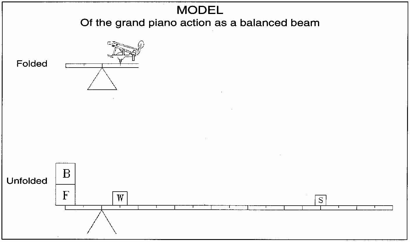
what engineers call a "folded beam" by use of the wippen and
shank levers. The New Touchweight Metrology
takes the folded beam of the action and "Unfolds" it into a
simple balanced lever such as the scale you might
find in your doctors office, where:
B = Balance Weight
F = Front Weight
W = Wippen Weight at the Key Ratio radius
S = Strike Weight at the Strike Ratio radius
Figure 1
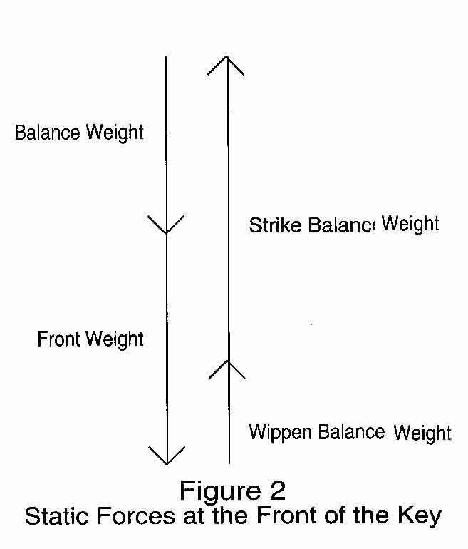
Figure 2 shows the balance of static forces at the
front of the key, where: The downward static force of the
Wippen Weight on the back of the key translates
through the Key Ratio to the upward force of the Wippen
Balance Weight at the front of the key, and: The
downward static force of the Strike Weight is multiplied
through the combined leverage of the shank, wippen,
and key to the upward force of the Strike Balance
Weight at the front of the key. The balance
of the upward and downward static forces at the front of the key
are expressed as the equation:
BalanceWt + FrontWt = (WippenWt x KeyRatio) + (StrikeWt
x StrikeRatio)
Definition & Determination Of The Units
Balance Weight- The amount of weight, placed
on the front of the assembled key that equals the upwards
static force at the front of the key. Balance
Weight is found by measuring UpWeight and DownWeight and
calculating:
Balance Weight = (DownWeight + UpWeight)/2
When measuring UpWeight and DownWeight the touch
weights are placed on the key centered on a point
13mm in from the front vertical edge of the key.
When the balance weight is placed on the front of the key it
is balanced and motionless as if it were a balanced
scale. Additional weight must be added to the balance
weight to overcome friction and start the key moving
down (DownWt) and weight subtracted from the
balance weight to start the key moving up (UpWt).
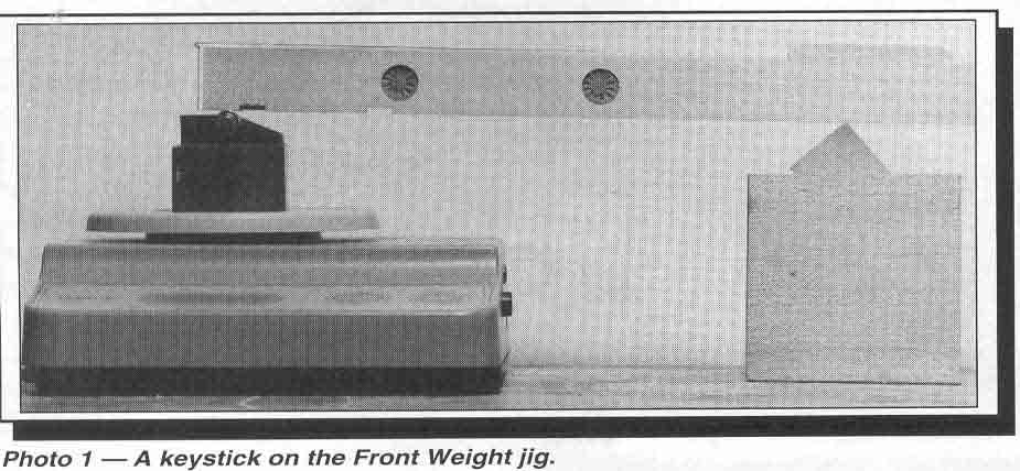
Front Weight- The radius weight of the keystick
pivoted on its balance point, taken at the front of the key. It
represents the downward static balancing force
at the front of the key.
Front weight is found by placing the key on a wedge
pivot so that the balance hole is centered across the
edge of the wedge. The front of the key rests
on a roller bearing which is on the pan of a digital scale. The
key is oriented in a horizontal attitude similar
to that when the key is at rest in the assembled action. The
roller bearing rests on a vertical axis through
a point on the surface of the key 13mm in from the front vertical
edge of the key (see Photo I).
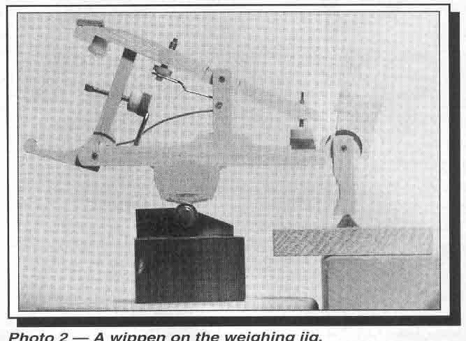
Wippen Weight- The radius weight of the wippen
pivoted on the wippen center, where the capstan contacts
the wippen heel. The wippen heel rests on
the roller at the capstan contact point. The wippen flange rests
on the felt wedge so that the wippen center is
aligned with the vertical axis through the
center of the roller. If necessary the flange
may be wedged with a sliver of wood to prevent the flange from
rotating (see Photo 2).
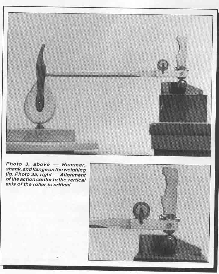
Strike Weight- The hammer weight plus the
radius weight of the hammer shank, pivoted at the hammer
flange, taken at Strike Line Radius. The
strike line of the hammer rests on the felt wedge block and the end
of the tipped up flange rests on the roller so
that the flange center aligns with a vertical axis through the
center of the roller. The height of the roller
is adjusted so that the shank rests horizontally. Playing cards can
be helpful as shims (see Photo 3).
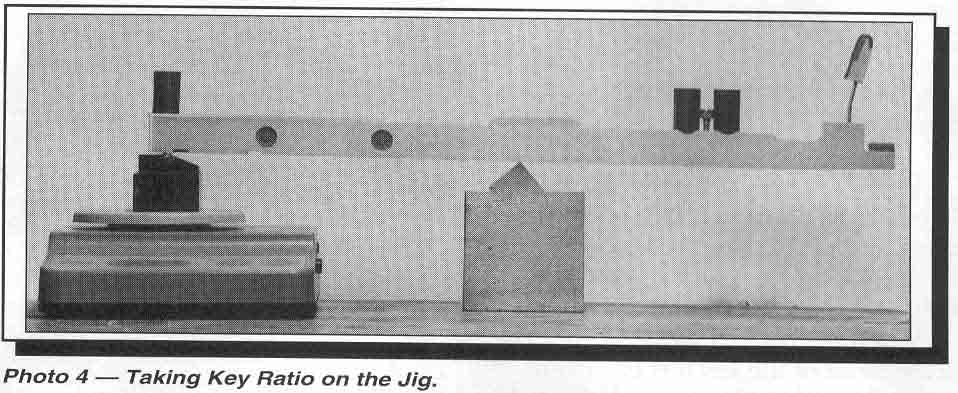
Key Ratio- The ratio of down- wards force
at the capstan to the corresponding upward force at the front of the
key. The key is set on the jig as for weighing
front weight. An amount of weight is placed on the front of the
key to make the front weight at least 70 grams.
This weight holds down the front of the key. The scale is
then tared to zero. (Digital scales have a tare
button which makes the scale read zero, regardless of what
weight is on the pan.) Two 50-gram weights are
placed on either side of the capstan so that there combined
center of gravity is at the capstan/heel contact
point. The scale will then read how the 100 grams translates
to the front of the key. For instance, if
the scale reading were -57.0 the key ratio would be 0.57 (see Photo
4).
Wippen Balance Weight- The upward static
force at the front of the key from the leveraged weight of the
wippen. Found by calculating:
WipBW = KeyRatio x WipWt
Top Action Balance Weight- The total upward
static force at the front of the key resulting from the leveraged
weight of the wippen, hammer, and shank.
Found as:
TopBW = BW + FrontWt
Strike Balance Weight- The upward static
force at the front of the key from the leveraged weight of the
hammer and shank.
Found by calculating:
StrikeBW = TopBW- WipBW
Strike Ratio - The amount of weight to balance
one gram of strike weight at the front of the key.
Found as:
Strike Ratio = StrikeBW/StrikeWt
Conclusion
The New Touchweight Metrology bridges from the
old Metrology of DownWeight and UpWeight through the
Balance Weight, thereby maintaining the connection
to traditional touchweight parameters. The array of
information provided by the New Touchweight Metrology
gives a wealth of information that has heretofore
remained hidden from us. Of particular utility
is the ability to measure hammer weight "on the shank" and
the calculation of Strike Ratio. The New Touchweight
Metrology provides a useful and relevant framework for
a more complete understanding of the balance of
piano action mechanisms.
The weights and measures described above only partially
describe the units and methods of the New
Touchweight Metrology. Other units and methods
will be described in future articles. In my next article I will
show the results of studies using the New Touchweight
Metrology and discuss the correlation between strike
ratio and leverage which leads to the ability to
rate the "dynamic" feel of piano actions using methodology of
the New Touchweight Metrology.
Notes:
1. To the best of my knowledge, the Balance Weight
value was first described by Don Galt, RPT, in
"Resistance in Piano Action," in the April, 1969
issue of the Piano Technicians Journal. He called it Weight
Resistance. In the October, 1990 Journal
is published a method for balancing keys to a specified Balance
Weight, by David C. Stanwood, RPT.
2. For this work, a scale needs to have 150-gram
capacity and resolution accuracy of 0.1 gram. The roller
bearing shown is an "idler bearing," which can
be purchased from small parts component suppliers. In a pinch,
an edge-trimming router bit can be used.
3. In all cases it is only necessary to carry the
decimal to the nearest tenth except for the "key ratio," which is
carried to the nearest hundredth.